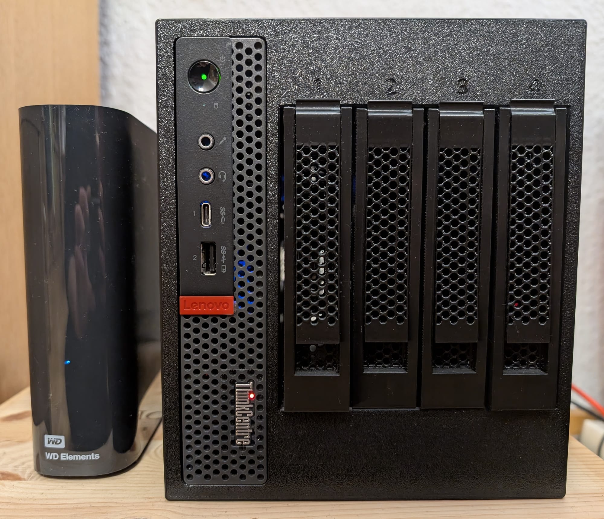
Building the 4-bay ThinkNAS with a Smart Fan Controller

A few months ago, a friend showed me a 3D print model for a ThinkCentre NAS. I was instantly intrigued and wanted to build it myself.

I don't have a 3D printer, so I asked the same friend to print it for me. In the meantime, I ordered all the extra materials I needed for it. I also noticed that the model designer recommends using a USB-A-powered fan controller for a 120mm fan that can be installed in the case and should run all the time. I found that a little annoying because I do not want the fan to spin all the time, even when it is not needed, which led me to craft a (somewhat) smart fan controller.
Bill of Materials
The bill of materials lists everything I used to build my ThinkNAS, and it is split into materials needed for the base model and additional materials needed for building the smart fan controller.
Materials needed for the base model
Click to expand/collapse the Bill of Materials for the base model
- Lenovo ThinkCentre M720q Tiny
- The 3D printed ThinkCentre NAS case itself [LINK]
- M720q riser card [LINK]*
- ASM1166-based PCIe to 6x SATA controller [LINK]*
- 4x SATA male to female adapters [LINK]*
- 4x SATA cables [LINK]*
- DC 5525 12V 6A power supply [LINK]*
- Alternatively to be absolutely sure that the power supply delivers enough (peak) power for four HDDs, choose a 12V power supply with ~10A [LINK]*
- DC 5525 to 4x SATA power splitter [LINK]*
- 120mm 4-pin PWM fan [LINK]*
- USB-A Fan Controller [LINK]*
- If you decide to build the smart fan controller below, then you won't need this
- 3D printed fan grill to prevent cables from obstructing the fan [LINK]
- 3D printed bracket for the PCIe SATA card [LINK]
- 6-32x6mm screws for putting the case together and installing HDD disks into the caddies [LINK]*
- M3x10mm screws for installing SATA adapters in the NAS case [LINK]*
- M3x25mm screws for installing handles to the HDD caddies [LINK]*
- Alternatively M3x22mm screws, but I have not tested this size specifically (see below for more information)
- M5x12mm self-tapping screws for installing the fan in the case [LINK]*
- Optionally: 3D printed 2.5" SSD to 3.5" HDD adapter, if you need to install SSDs in the NAS case (printing it in PETG is enough, ABS, as the print profile suggests, is not really needed) [LINK]
Additional materials for the smart fan controller
- ESP32-C3 SuperMini [LINK]*
- AHT20 temperature sensor module [LINK]*
- MT3608 DC-DC boost converter module [LINK]*
- USB-A to USB-C cable [LINK]*
- Preferably with USB data lines (D+/D-) to allow for reading the serial output and reflashing code from the ThinkCentre, but not necessarily needed
- Those 10-20cm cables that often come free with various electronic devices usually lack the data lines, but will still power the microcontroller
- Any double-sided tape for securing the fan controller inside the case
- You probably have something lying around; otherwise, this is what I used (20mm wide, 1mm thick): [LINK]*
Building the "dumb" NAS case
I'll skip most of the assembly of the base NAS case itself, as it was pretty unspectacular and mostly involved following the manual provided by the model designer. The images in the manual were sometimes taken from too short a distance, so you can't really see where a component is supposed to go. Despite that, it was still quite straightforward to assemble the "backplane" (what the model designer calls the part where the SATA adapters are installed and which is inserted into the outer case) and screw everything together. The truly interesting part is replacing the USB fan controller recommended by the model designer with a smart one.
I ordered all the parts listed in the original bill of materials provided by the model designer, only to notice that the listed screw length for installing the caddy handles was too short. The model designer recommends M3x20mm screws, but you should use longer ones. I used M3x25mm because those are more readily available than any between 20 and 25 mm, but they are slightly too long. If they are fully screwed in, they stick out slightly on the other side of the handle, but screwing them in almost all the way so they do not, or only slightly, stick out works without any problems. I imagine that something like M3x22mm is the sweet spot.
The model designer also recommends installing a fan grill to prevent cables from jamming the fan. I forgot to have this part printed at first, and it annoyed me very much during the initial installation. The problem was that I'd already disassembled the old setup, and waiting for the part to continue building was infeasible, so I needed to make it work somehow. The temporary fix was to use an absurd number of cable ties to secure all the cables so they did not obstruct the fan. In the meantime, I had a fan grill printed and installed it a few weeks later.
Here are some time lapses of the prints:
Printing time lapses
Outer case of the ThinkNAS
Inner part of the ThinkNAS ("backplane") that is inserted into the outer case
The SATA adapters are installed into these four parts which are then installed into the inner part of the case
Two caddies
Even more caddies
Four caddy handles
2.5" SSD to 3.5" HDD Adapter for the boot SSD
Fan grill
Smart Fan Controller
While researching how to make a temperature-controlled or "smart" fan controller, I came up with a few different ways. The first idea was to use a fan header splitter to duplicate the CPU fan control signals for the fan inside the NAS case. This method may work for other SFF computers and 3D models, but it doesn't work with the M720q without a lot of tinkering. The problem is that the CPU fan header on this machine has a nonstandard layout where some pins are switched, so a standard 4-pin PWM fan header does not work here. I also thought that this approach was suboptimal because the CPU temperature could differ from the actual temperature inside the case.
After abandoning the previous idea, I found the KlausMu/esp32-fan-controller GitHub project, which uses an ESP32 and a few other components to make a temperature-controlled fan controller that can connect to Home Assistant via MQTT. I didn't need the Home Assistant features, and I'm quite happy with every device that does not need a Wi-Fi connection, so I looked into how I could approach this project using that as inspiration.
I've worked with a few temperature sensors in previous projects (maybe I'll write about them in future blog posts, stay tuned!), and the AHT20 seemed like a good candidate, as it's accurate enough for my use case and cheap. I also had an ESP32-C3 SuperMini and some MT3608 DC-DC boost converter modules lying around, so I started soldering all the components together. (Maybe not the smartest idea to solder everything before testing it on a breadboard, but it worked out mostly fine for this project.)
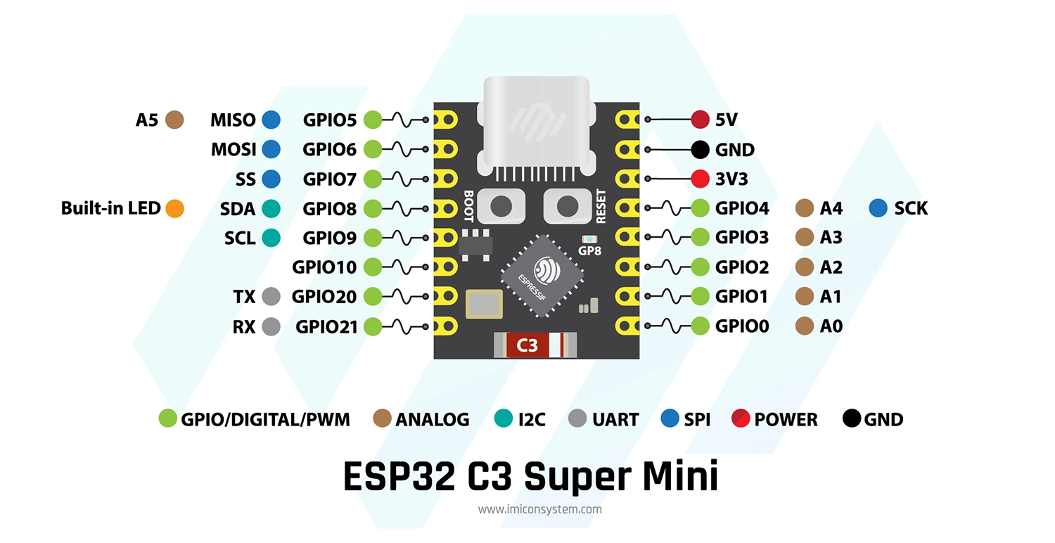
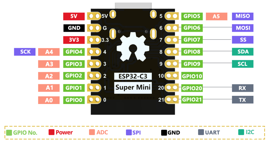
The following ESP32-C3 SuperMini pinout diagrams may help with the wiring later to show which wire connects to which pin of the microcontroller.
I used the following wiring for the fan controller, but as it later turned out, although it works, it is not ideal.
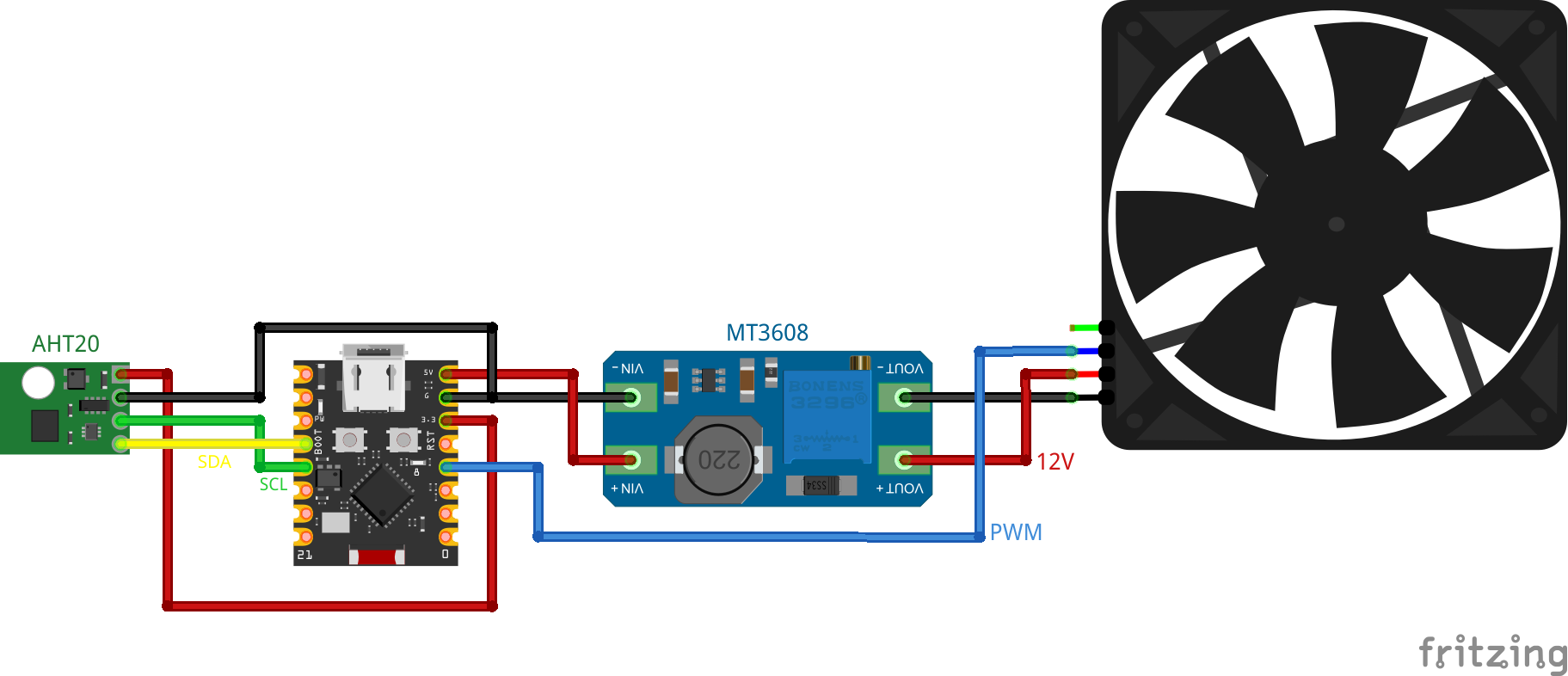
I only noticed this after soldering everything together, but there's a small blue LED on GPIO8 of the ESP32-C3 SuperMini. If you use my code and wiring, this LED will blink every time the microcontroller communicates with the temperature sensor because it's connected to the default SDA pin GPIO8. If this annoys you, use different pins than GPIO8 (and GPIO9) for I²C and different pin assignments in the code below. For example, GPIO0 and GPIO1 should work without any problems, as these pins do not have any secondary assignments like the blue LED on GPIO8. I also connected the PWM pin of the fan to GPIO3 of the microcontroller. Luckily, this pin does not need to be changed, like the one for SDA. So, if you want to build this fan controller as well, I recommend the following wiring:
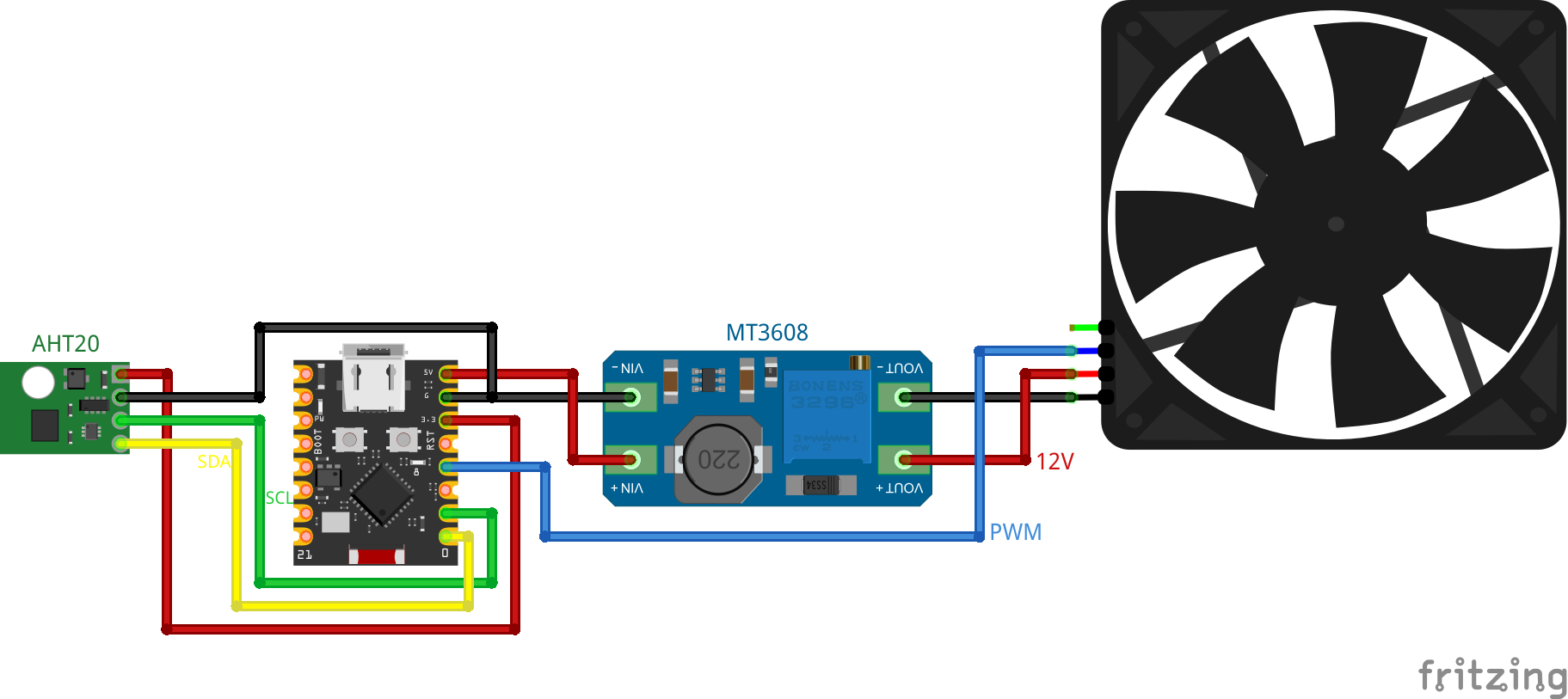
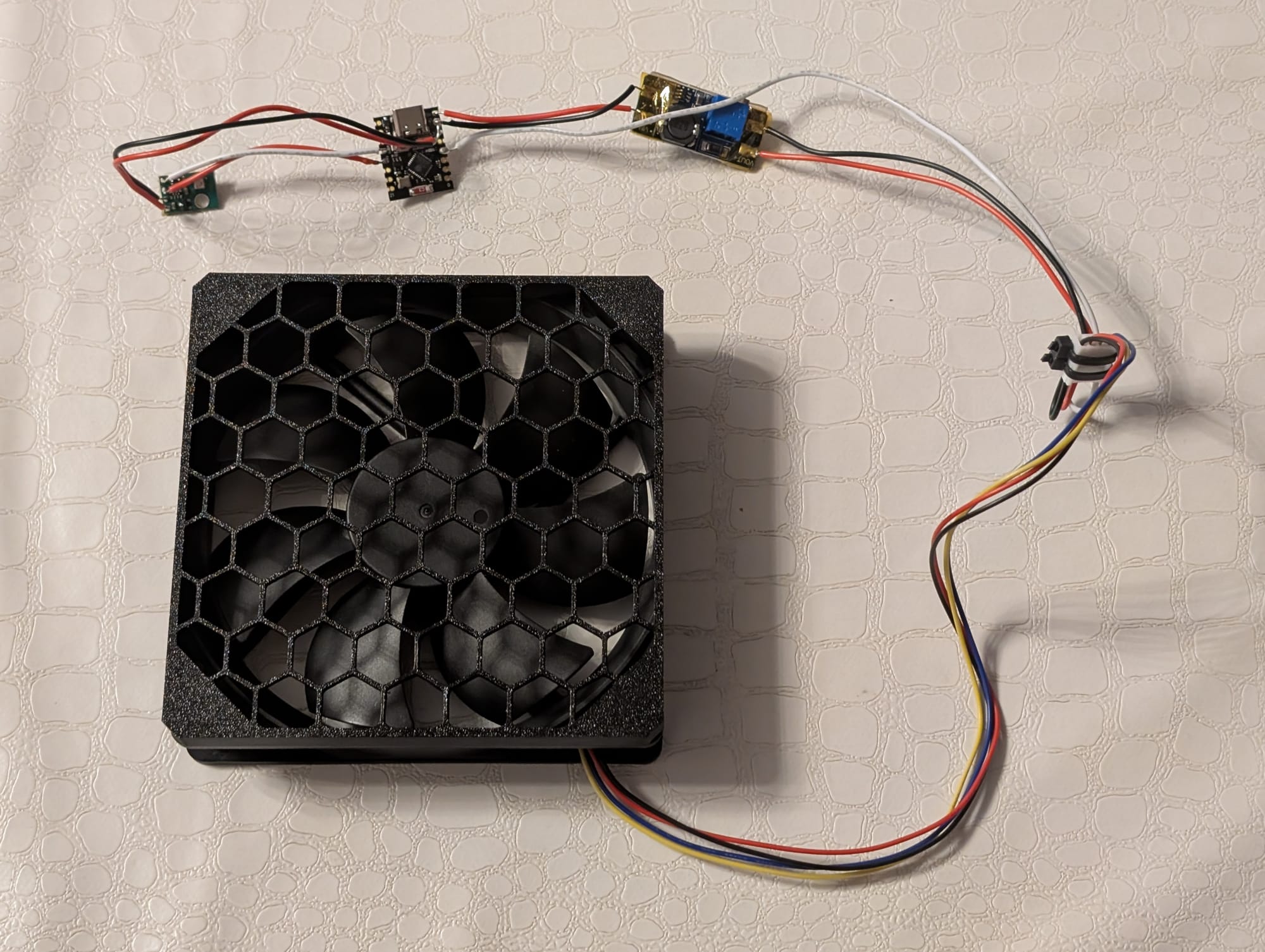
All the other connections are self-explanatory: the AHT20 is connected to 3.3V and ground of the microcontroller, the input side of the MT3608 is connected to 5V and ground of the microcontroller, and the output side of the MT3608 is connected to 12V and ground of the fan. I also isolated most of the pins with budget-brand Kapton tape, as at that point in the project I was unsure whether there would be exposed metal inside the assembled case that could short out the circuit. The assembled fan controller should look something like this (if you decide to plaster the components with Kapton tape as well):
The programming of the microcontroller was straightforward. I struggled a little to install firmware on it the first time, but then I found out that you need to hold the BOOT button (or manually pull GPIO9 low) on the device while connecting it to the computer to allow flashing. Otherwise, the microcontroller will continuously connect and disconnect from the computer every second.
I also recently started using PlatformIO for my microcontroller projects instead of the Arduino IDE because it offers more flexibility and makes working with multiple source files possible, at the cost of not having an "everything just works out of the box" experience. The code is still quite minimal and should work without prior experience.
If you do not already have PlatformIO installed, search the VSCode extension store for "PlatformIO" and install the extension "PlatformIO IDE" (more information on the PlatformIO website). Create a new project in PlatformIO, overwrite the existing platformio.ini with the one below, and paste the two code files config.h and main.cpp into the src/ folder. There are some settings in config.h that you can change, such as the pin assignments for SDA and SCL or toggling serial logging.
If you do not want to install PlatformIO, you can also create a new Arduino IDE project and paste in smart_fan_controller.ino (which is essentially just a merged config.h and main.cpp file). Then you need to install the esp32 board manager (link to tutorial) and select the board type Nologo ESP32C3 Super Mini. You can also change the previously mentioned settings with this approach at the top of the .ino file.
platformio.ini
; PlatformIO Project Configuration File
;
;   Build options: build flags, source filter
;   Upload options: custom upload port, speed and extra flags
;   Library options: dependencies, extra library storages
;   Advanced options: extra scripting
;
; Please visit documentation for the other options and examples
; https://docs.platformio.org/page/projectconf.html

[env:nologo_esp32c3_super_mini]
platform = https://github.com/pioarduino/platform-espressif32/releases/download/55.03.37/platform-espressif32.zip
board = nologo_esp32c3_super_mini
framework = arduino
monitor_speed = 115200
upload_speed = 921600
lib_deps = adafruit/Adafruit AHTX0@^2.0.5
platformio.ini
config.h
// ----------------------
// --- Debug Settings ---
// ----------------------

// set to 1 to enable serial output
#define DEBUG 1

#if DEBUG
    #define D_begin(...) Serial.begin(__VA_ARGS__)
    #define D_waitForSerial() while (!Serial) { delay(100); }
    #define D_print(...) Serial.print(__VA_ARGS__)
    #define D_println(...) Serial.println(__VA_ARGS__)
    #define D_printf(...) Serial.printf(__VA_ARGS__)
    #define D_write(...) Serial.write(__VA_ARGS__)
#else
    #define D_begin(...)
    #define D_waitForSerial()
    #define D_print(...)
    #define D_println(...)
    #define D_printf(...)
    #define D_write(...)
#endif // DEBUG

// -----------------------
// --- Pin Definitions ---
// -----------------------

// pin for PWM fan control
#define PIN_PWM 3

// pin for SDA
#define PIN_SDA 8

// pin for SCL
#define PIN_SCL 9

// --------------------
// --- PWM Settings ---
// --------------------

// PWM frequency in Hz
#define PWM_FREQUENCY 25000

// PWM resolution in bits
#define PWM_RESOLUTION 8
config.h
main.cpp
#include <Arduino.h>
#include <Adafruit_AHTX0.h>

#include "config.h"

Adafruit_AHTX0 aht;

float get_temperature() {
    sensors_event_t aht_humidity, aht_temperature;

    aht.getEvent(&aht_humidity, &aht_temperature);

    return aht_temperature.temperature;
}

void setup() {
    D_begin(115200);
    D_waitForSerial();

    ledcAttach(PIN_PWM, PWM_FREQUENCY, PWM_RESOLUTION);

    Wire.begin(PIN_SDA, PIN_SCL);
    aht.begin(&Wire);
}

void loop() {
    // request the current temperature from the AHT20
    float case_temp = get_temperature();

    uint8_t duty_cycle = 0;

    // if PWM resolution is set to 8bit, ledcWrite uses an 8bit duty cycle value (0-255)
    // currently implemented temperature steps are:
    // <27°C (no cooling), <30°C, <40°C, <50°C and >=50°C
    if (case_temp < 27.0f) {
        duty_cycle = 0;
    } else if (case_temp < 30.0f) {
        duty_cycle = 50;
    } else if (case_temp < 40.0f) {
        duty_cycle = 80;
    } else if (case_temp < 50.0f) {
        duty_cycle = 100;
    } else {
        duty_cycle = 150;
    }

    // set PWM
    ledcWrite(PIN_PWM, duty_cycle);

    // print the current temp and fan duty cycle to serial, if enabled
    D_printf("Current case temperature: %.2f°C\nSet fan to %u\n", case_temp, duty_cycle);

    delay(5000);
}
main.cpp
smart_fan_controller.ino
#include <Arduino.h>
#include <Adafruit_AHTX0.h>

// ----------------------
// --- Debug Settings ---
// ----------------------

// set to 1 to enable serial output
#define DEBUG 1

#if DEBUG
    #define D_begin(...) Serial.begin(__VA_ARGS__)
    #define D_waitForSerial() while (!Serial) { delay(100); }
    #define D_print(...) Serial.print(__VA_ARGS__)
    #define D_println(...) Serial.println(__VA_ARGS__)
    #define D_printf(...) Serial.printf(__VA_ARGS__)
    #define D_write(...) Serial.write(__VA_ARGS__)
#else
    #define D_begin(...)
    #define D_waitForSerial()
    #define D_print(...)
    #define D_println(...)
    #define D_printf(...)
    #define D_write(...)
#endif // DEBUG

// -----------------------
// --- Pin Definitions ---
// -----------------------

// pin for PWM fan control
#define PIN_PWM 3

// pin for SDA
#define PIN_SDA 8

// pin for SCL
#define PIN_SCL 9

// --------------------
// --- PWM Settings ---
// --------------------

// PWM frequency in Hz
#define PWM_FREQUENCY 25000

// PWM resolution in bits
#define PWM_RESOLUTION 8

// -----------------------

Adafruit_AHTX0 aht;

float get_temperature() {
    sensors_event_t aht_humidity, aht_temperature;

    aht.getEvent(&aht_humidity, &aht_temperature);

    return aht_temperature.temperature;
}

void setup() {
    D_begin(115200);
    D_waitForSerial();

    ledcAttach(PIN_PWM, PWM_FREQUENCY, PWM_RESOLUTION);

    Wire.begin(PIN_SDA, PIN_SCL);
    aht.begin(&Wire);
}

void loop() {
    // request the current temperature from the AHT20
    float case_temp = get_temperature();

    uint8_t duty_cycle = 0;

    // if PWM resolution is set to 8bit, ledcWrite uses an 8bit duty cycle value (0-255)
    // currently implemented temperature steps are:
    // <27°C (no cooling), <30°C, <40°C, <50°C and >=50°C
    if (case_temp < 27.0f) {
        duty_cycle = 0;
    } else if (case_temp < 30.0f) {
        duty_cycle = 50;
    } else if (case_temp < 40.0f) {
        duty_cycle = 80;
    } else if (case_temp < 50.0f) {
        duty_cycle = 100;
    } else {
        duty_cycle = 150;
    }

    // set PWM
    ledcWrite(PIN_PWM, duty_cycle);

    // print the current temp and fan duty cycle to serial, if enabled
    D_printf("Current case temperature: %.2f°C\nSet fan to %u\n", case_temp, duty_cycle);

    delay(5000);
}
I haven't yet extensively tested the implemented temperature steps and corresponding PWM duty cycles for the fan. They're set to values that make sense to me and seem to work well in my case but may need a bit of tweaking. If I find better values, I'll update the code snippets above and add a notice at the top of the post.
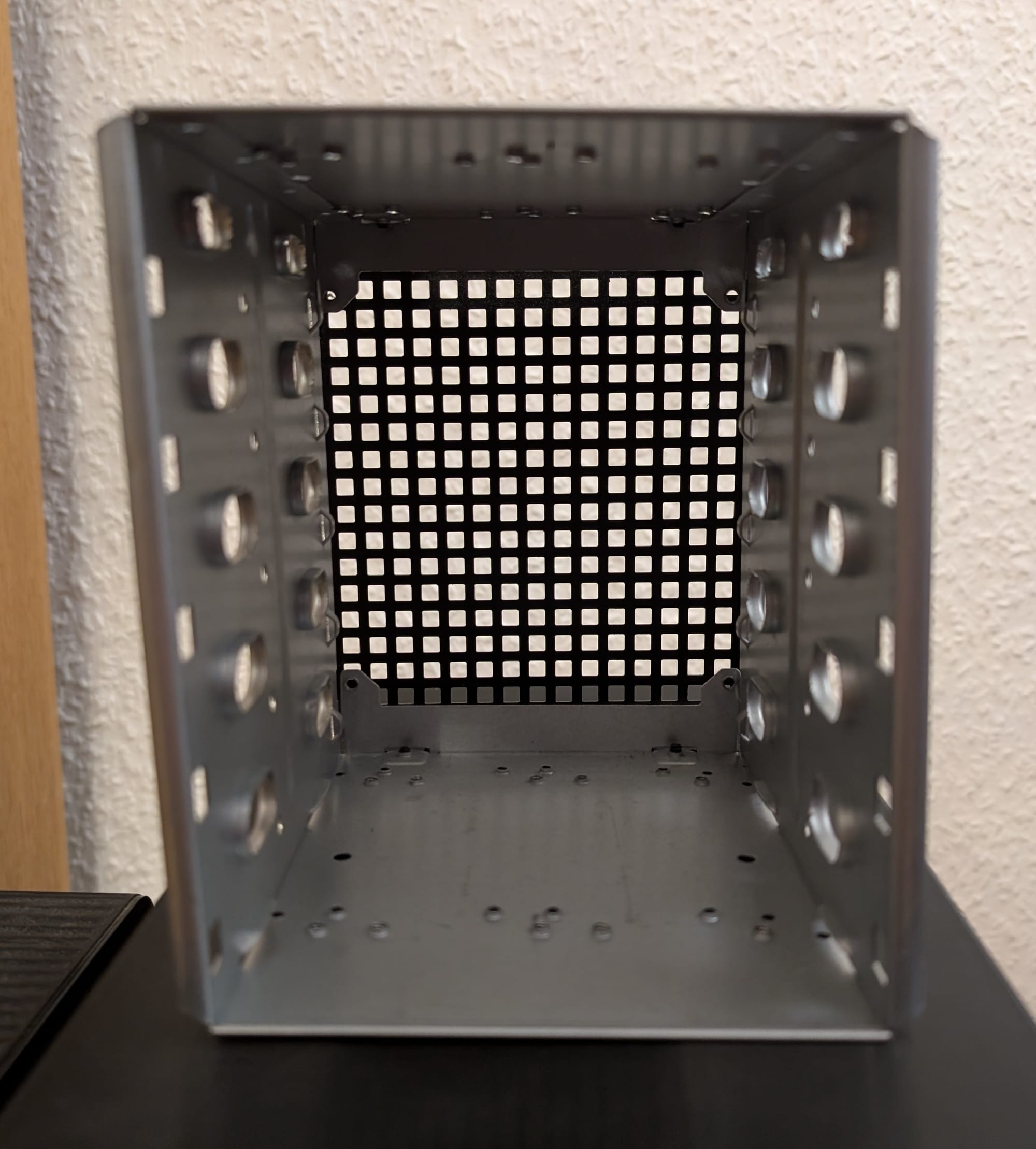
After programming the microcontroller, the fan controller could be installed in the case. I used double-sided tape on the back of the boost converter to stick it underneath the "backplane". This way, the temperature sensor hovers perfectly behind the HDDs and in front of the fan. Your mileage may vary depending on how you soldered your components together, how long your wires are, etc.
Now came the installation of the boot SSD and the HDDs. This step was really frustrating because there was some wiggle room between the caddies and the slots they slide through. The SATA adapters also seemed to be ever so slightly misaligned with the caddies. This made it quite hard to tell whether an inserted SSD/HDD was actually fully connected to the SATA adapter in the back of the case. The best method appeared to be wiggling the caddy a little to feel the SATA adapter in the back while inserting it into a slot. To make full contact with the SATA adapter, a small bit of force may be needed. After some trial and error, the HDDs were successfully connected to the adapters, but they still felt a little loose, and I could not be bothered to improve this anymore. The HDDs have stayed in their slots, though, so it seems to hold for the time being.

The assembled ThinkNAS looks very clean, and I have yet to encounter any issues since putting it together. There have been no overheating problems yet, though that will truly be put to the test when the next modded Minecraft server is started ;)
The finished build is a night-and-day difference compared to the HDD cage from before. The HDD cage was actually quite practical. It had five 3.5" slots and space to install a 120mm fan in the back, but it was really ugly.
(I sadly do not have a picture of the assembled HDD cage build, only of the cage itself.)
Total Project Costs
The total price, excluding printing costs, comes out to about $53.31 or 47,33€. This price includes items from the previous HDD cage build that I could reuse and some things I already had lying around, like SATA cables and MT3608 DC-DC boost converters. I also used some AliExpress gimmicks (e.g., coins) to save a bit of money, so it may not be representative if you decide to buy all components now. The prices for the screws assume the complete ordered supply is used, but there are a lot left over. If you account only for the screws that were actually used (or you already have similar screws to copy this build), it is a few bucks cheaper.
Cost breakdown
| product | ppu_usd | usd_eur | ppu_eur | units | price_usd | price_eur |
|---|---|---|---|---|---|---|
| M720q riser card | 8,73 | 0,8932 | 7,797636 | 1 | 8,73 | 7,797636 |
| PCIe SATA Controller | 18,38 | 0,8868 | 16,299384 | 1 | 18,38 | 16,299384 |
| 4x SATA adapter | 2,13 | 0,8659 | 1,844367 | 1 | 2,13 | 1,844367 |
| SATA cable | 1,06 | 0,8864 | 0,939584 | 4 | 4,24 | 3,758336 |
| DC 5525 power supply | 6,53 | 0,8932 | 5,832596 | 1 | 6,53 | 5,832596 |
| DC 5525 SATA power splitter | 5,01 | 0,8932 | 4,474932 | 1 | 5,01 | 4,474932 |
| 12V PWM fan | 2,68 | 0,8636 | 2,314448 | 1 | 2,68 | 2,314448 |
| 6-32x6mm screws | 1,06 | 0,8659 | 0,917854 | 1 | 1,06 | 0,917854 |
| M3x10mm screws | 0,38 | 0,8659 | 0,329042 | 1 | 0,38 | 0,329042 |
| M3x25mm screws | 0,40 | 0,8614 | 0,344560 | 1 | 0,4 | 0,344560 |
| M5x12mm screws | 0,47 | 0,8640 | 0,406080 | 1 | 0,47 | 0,406080 |
| ESP32-C3 SuperMini | 1,26 | 0,9793 | 1,233918 | 1 | 1,26 | 1,233918 |
| 5x MT3608 module | 1,75 | 0,9497 | 1,661975 | 0,2 | 0,35 | 0,332395 |
| AHT20 module | 0,47 | 0,8534 | 0,401098 | 1 | 0,47 | 0,401098 |
| USB-A USB-C cable | 0,38 | 0,8506 | 0,323228 | 1 | 0,38 | 0,323228 |
| double-sided tape | 0,84 | 0,8614 | 0,723576 | 1 | 0,84 | 0,723576 |
| TOTAL | $53.31 | 47,33€ |
I actually thought the total costs would be a little lower before I calculated this breakdown, but it's still much more affordable than "real" NAS systems, and the finished build looks really nice :)
Final Thoughts
The finished ThinkNAS looks really good, and it's definitely a nice upgrade compared to the HDD cage I had before. There were some frustrating aspects of this build, including the wrong screw size listed for the HDD caddy handles, having to wiggle the HDDs/SSDs into the SATA adapters to make them connect properly, and forgetting to print a fan grill (which is entirely my fault). Other than that, if you have an M720q or M920q ThinkCentre in your homelab and are planning to hook up some disks, I can recommend this build!